History
A 65-year-old male patient, struck by a car while cycling, was admitted to the Department of Traumatology. The patient had no recollection of the incident and his vital parameters had remained stable during transportation. There were no observed sensory or motor deficits. A CT scan was performed on an energy-integrating detector (EID) CT, which revealed multiple fractures of the cervical spine. 24 hours later, a control CT examination was performed on a newly introduced single source photon-counting detector (PCD) CT, NAEOTOM Alpha.Prime, for assessment.
Diagnosis
PCD CT images revealed a non-displaced, unstable fracture of the base of the C2 dens (IIIA – C2 type A N0), [1] which was not seen in the previous EID CT images (Fig. 1). Other findings, including dislocated fractures of the left anterior and posterior arches of the C1 vertebra (Jefferson fracture) and a left massa lateralis avulsion fracture with the dens axis dislocated to the left (IIB – C1 type B N0) (Fig. 2); [2] [3] fractures of the foramina transversaria of the C3 (left, dislocated) and the C4 (right, non-dislocated) (type A0 N0), the spinous processes of the C4 and C6 (type A0 N0), bilateral arcus of the C7 (type A0 BL F1) and the head of the first rib on the left (Fig. 3), showed no noticeable changes. AO classification was applied. [4]
The patient underwent conservative treatment with a collar. A follow-up 3 months later showed no progression or instability.
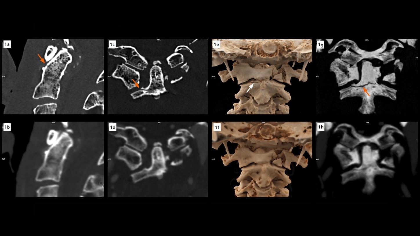
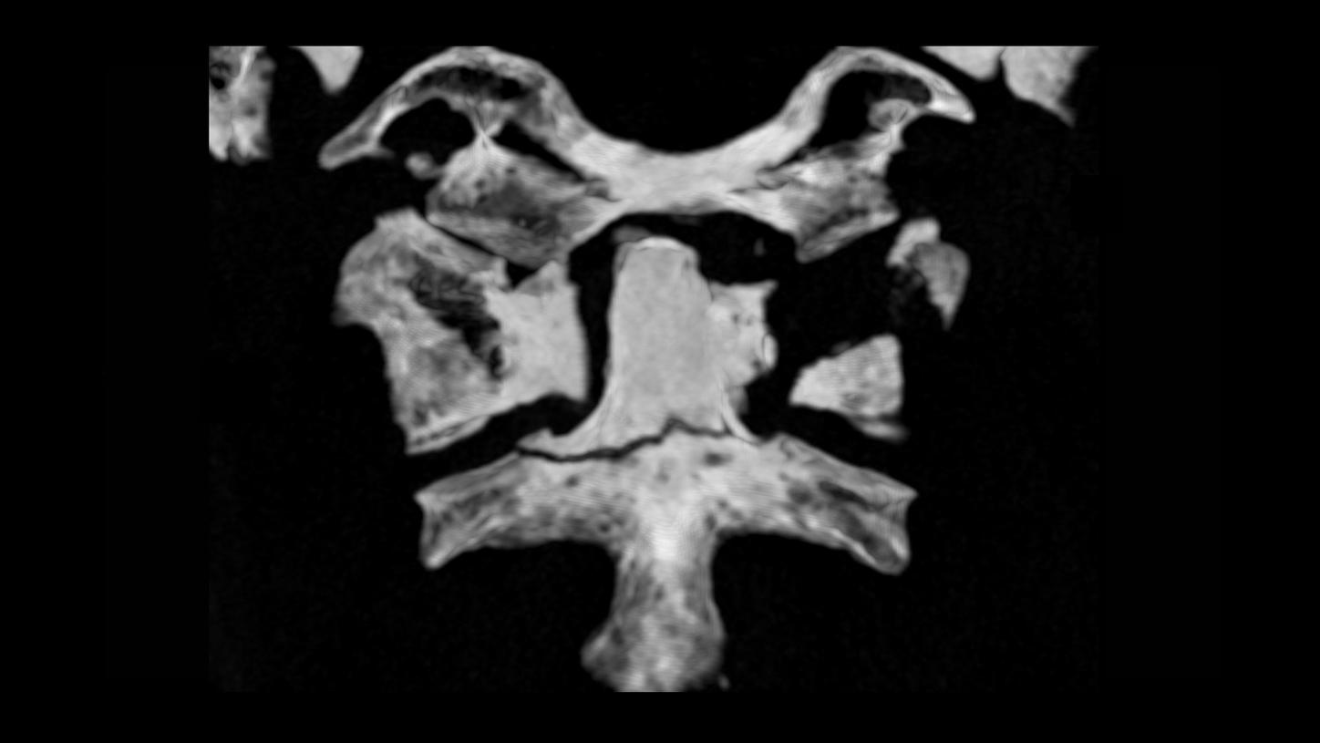
Fig. 1: A fracture of the base of the C2 dens (arrows), not seen in the EID CT images (lower row), is clearly seen in the PCD images (upper row). The visibility of the fracture line is improved in the thin slab MIP images (Figs. 1g and 1h).
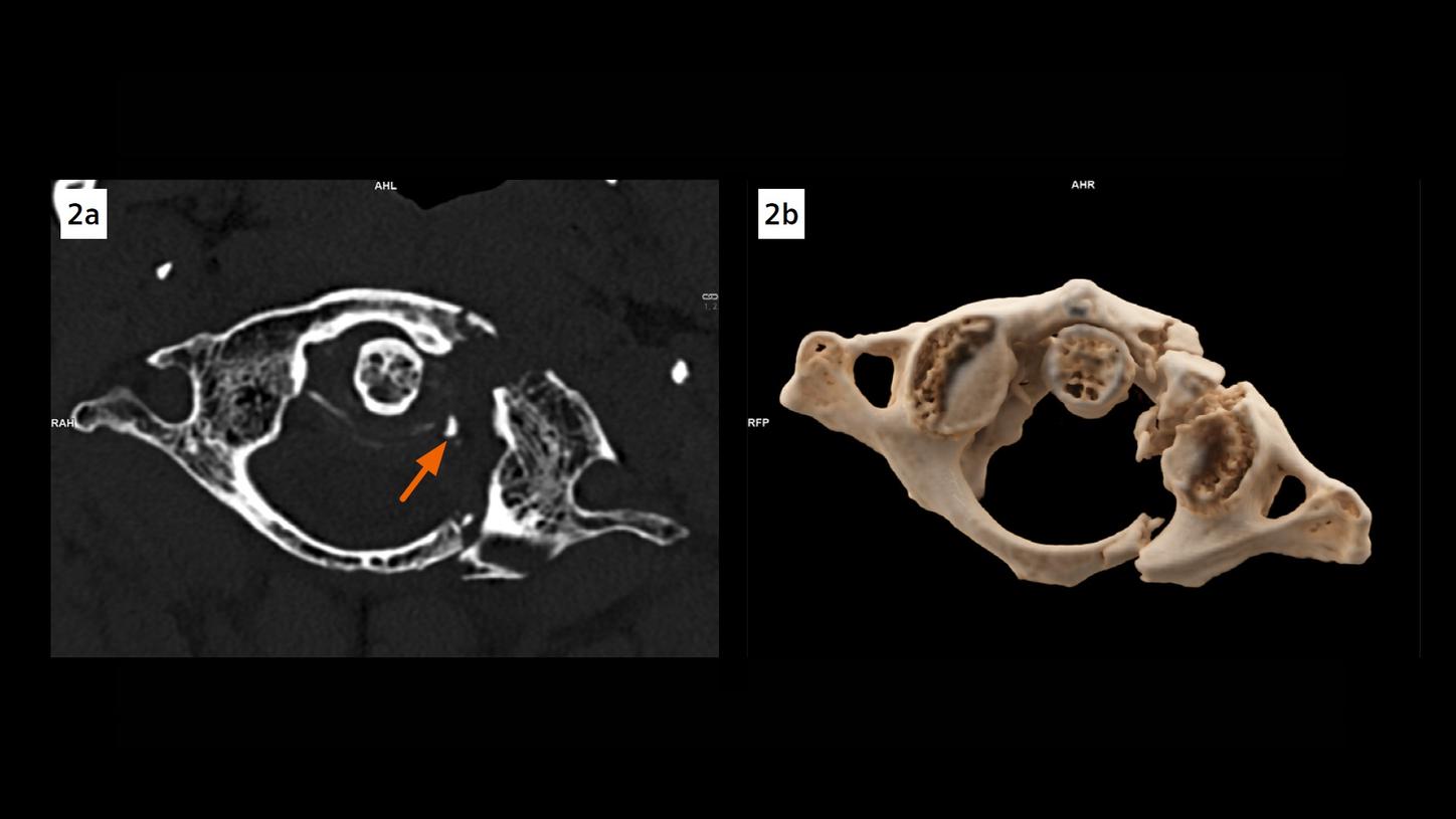
Fig. 2: An axial image (Fig. 2a) and a cVRT image (Fig. 2b) show dislocated fractures of the anterior and posterior arches of C1 and a left massa lateralis avulsion fracture (arrow), with the dens axis dislocated to the left.
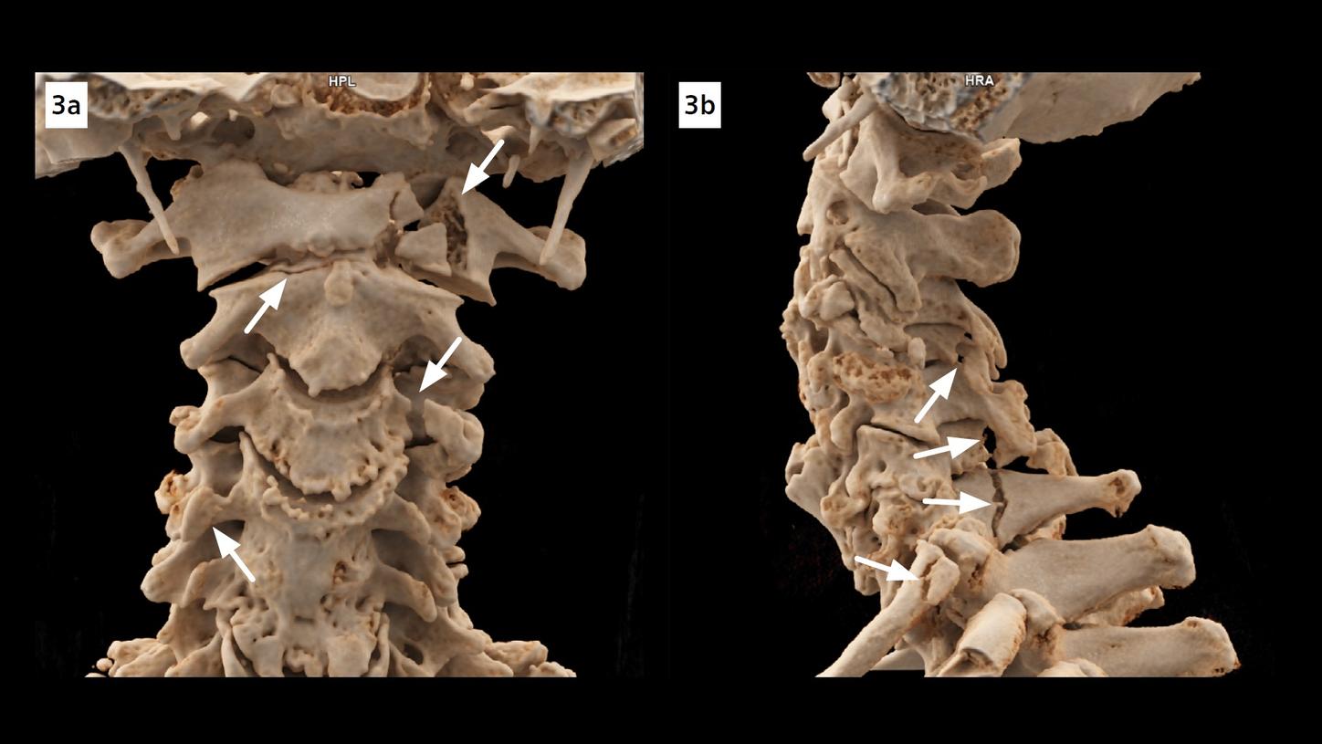
Fig. 3: cVRT images show fractures (arrows) of the C1, C2 dens, foramina transversaria of the C3 and the C4, spinous processes of the C4 and C6, bilateral arcus of the C7 and the head of the first rib on the left.
Comments
Fractures of C2 dens, or odontoid process, are commonly classified by the Anderson and D’Alonzo classification system. A fracture at the base of the dens, such as this case, is classified as Type 2. This type of fracture is unstable due to its location and the potential of displacement or non-union. If not recognized in time, it could potentially lead to serious health impairment or an increased risk of mortality especially in older adults.
In this case, the dens fracture, not shown in EID CT images acquired at 0.625 mm, is depicted in PCD CT images acquired at 0.4 mm, owing to an increased spatial resolution. PCD has a smaller pixel electrode size, which decreases the partial volume effects and blooming artifacts. Its detector elements are separated by electric fields, instead of physical separators applied in EID, resulting in an increased efficiency of X-ray photon utilization and signal-to-noise ratio.
The high-resolution images, acquired routinely at thin slices and reconstructed with a sharper kernel for cervical spine, can also be used to create three dimensional images, with cinematic rendering technique (cVRT), for an in-depth, lifelike visualization of the fractures in detail. This facilitates the communication between physicians and helps in treatment planning. In trauma settings, PCD CT, with its increased spatial resolution in routine scans, may benefit the clinical outcome of the patients.
Examination Protocol